
AUTOMATIC MACHINES AND WORKING FINISHING LINES
FOR PROFILES WOOD-MDF-PVC-POLYSTYRENE


![]()


|
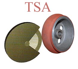
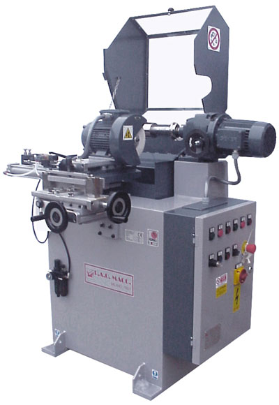
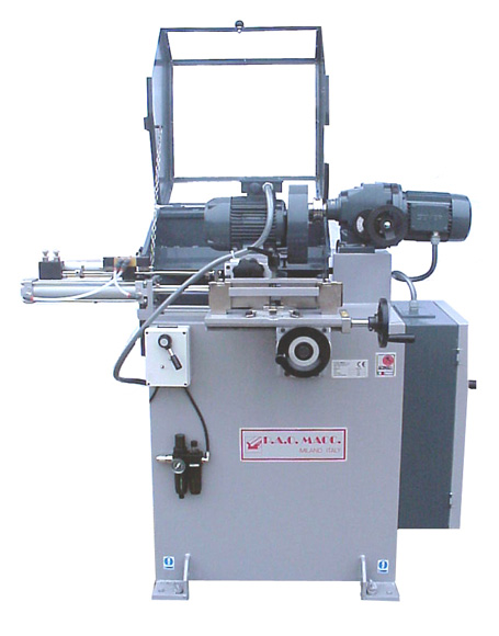
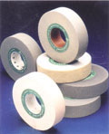
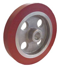
AUTOMATIC WHEELS SHAPER MACHINE FOR SILICONE WHEELS AND ABRASIVE SANDING WHEELS
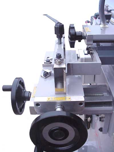
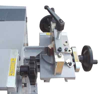
General descriptions of the machine. The machine consists of a variable-speed drive which can be regulated from 350-1750 rpm, on whose shaft the silicone wheel to be shaped can be mounted. The wheel-holder shaft has a diameter of 25 mm and length of 110 mm and is fitted with spacers in order to mount the wheel in the required position. A second motor is mounted on a rocking trolley and is provided with an abrasive wheel for cutting. The rocking trolley is driven by a pneumatic cylinder and a hydraulic brake unit which produces a fluid and even stroke. The speed of the trolley can be regulated by means of chokes installed on the brake unit. A second trolley is mounted on this one, at 90° to it, and is sprung by means of a sensing elastic band. A feeler pin is mounted on this trolley to act as a copier, i.e. following the profile of the frame. At the other end of the second trolley the tool-holder motor is mounted which, controlled by the feeler pin, copies exactly the shape of the profile and reproduces it on the silicone wheel mounted on the shaft of the variable-speed drive (the latter is fixed).
Description of the first rocking trolley : The first rocking trolley has a stroke parallel to the silicone wheel and consists of a unit with a pneumatic cylinder with 300 mm stroke and a hydraulic brake assembly. The longitudinal movement obtained in this way is even and easily controlled by two chokes which govern the speed of movement. The rocking movement is obtained by a pneumatic valve with double automatic piloting. The stroke can be adjusted by moving the two cursors which act mechanically on the pilots of the valve (for greater detail consult the user instructions, in the enclosures). The whole unit rocks by means of a T guide and cursor with extremely high precision. Description of the second trolley The second trolley, also placed on a track and cursor like the first one described above, is sprung by the use of a sensing elastic band. A slide with groove mounted on the trolley allows the shaping wheel to approach the silicone wheel; the shaper motor is mounted on this slide. At the other end of the motor there is an adjustable feeler pin which traces the shape of the profile. Through the force of the return elastic band the whole shaper motor assembly is forced to follow the movement of the feeler pin. Profile-holder turret The profile-holder turret supports the rod sample from which the counter-profile to be obtained is mounted. The turret is mounted by a cross movement performed by means of 2 slides with grooves; two hand wheels enable the required positioning to be carried out. The turret can also be tilted, hence tilting the profile too. The degrees of tilting used during shaping must correspond to the Set-Up of the head where the wheel is to be used. The profile is clamped on the turret by means of a screw hook whose height can be adjusted (the height of the profile must not exceed 30 mm). At the sides of the profile there are two sliding fins which must rest on the external sides of the profile part. This is to prevent the feeler pin, sliding over the end part of the profile, from coming up against an excessively high step between the fins and the profile itself. The profile is rested against an adjustable reference guide and then locked by means of appropriate clamping. In any case the stroke has to be limited exactly in the point where the counter-profile is to produced. |
TSA - TECHNICAL DETAILS
LENGTH :1.200 mm.
WIDTH :1.050 mm.
HEIGHT :1.250 mm.
WEIGHT :280 KG.
Installed Power : Kw. 1,3
Wheel motor Power : Kw. 0.75
Grinding wheel motor power : Kw. 0.75
Compressed air pressure : 6 Bar (90 PSI)
Air requirements : 40 nl/min SCFM 1.4
Wheel speed variator shaft : D.25 mm. x 110
Grinding wheel diameter : D. 180 mm.


ASK FOR OUR COMPLETE CD MULTIMEDIA PRESENTATION
Copyright(c) 2009 - paomacc group-
info@paomacc.net